2026-09-21
Using AI large language models for piping design.
Written by: Peter Maginot
I’ve been toying around with linking CAD software up with Claude Code to draft up piping arrangements based on sketches, existing drawings, and pictures. LLM’s are shockingly good at translating written directions into computer code, and sure enough, that extends to interpreting sketches, drawings, and photographs to generate code to drive CAD software to model piping too.
After practicing on a whole bunch of examples, I’ve put together a markdown file that can guide an AI agent to turn a sketch or set of photographs into a full model. It’s written for FreeCAD but the same techniques could also be applied to AutoCAD or any other commercial piping design software that allows the use of macros or the model context protocol to allow the AI to direct the software.
Here’s an example. I threw together some pipe and fittings I had in my basement, took a few pictures, added a few annotations to those pictures, and then prompted the following with Claude Opus 5 running in Visual Studio Code with the repository linked above:
Create a FreeCAD model of the piping arrangement shown in the photos in @examples/photo_example . Reference @docs/freecad-quetzal-guide.md . All pipes are 3/4” and 1/2” nominal diameter Schedule 40. All tees and elbows in the photos are 150# socket fittings. Model all fittings as 3000# socket fittings. Note that the photograph’s fittings won’t exactly match the dimension of the Quetzal model. This may require adjusting the length of individual pipes so that the fitting work points match the dimensions given in the photograph with the tape measure. Tape measure lengths are given in inches.
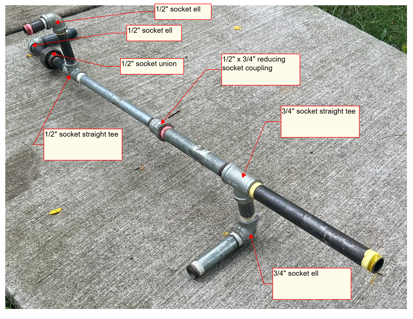
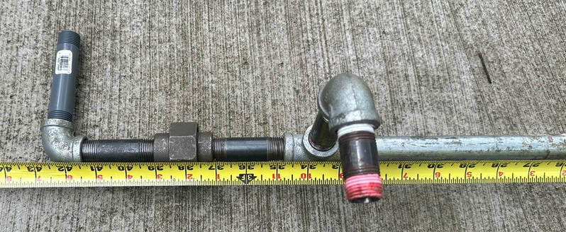
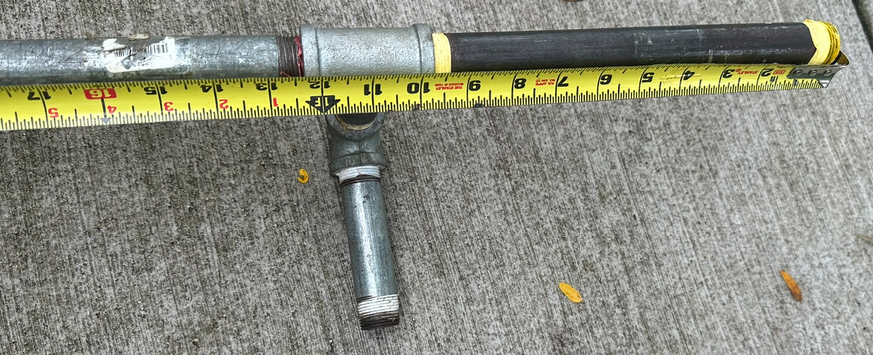
It churned for about five minutes, asked a few clarification questions, and then spit out a model.
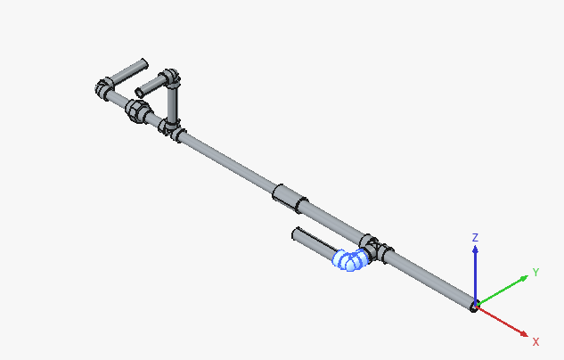
Ah, almost there, but screwed up the roll angle on one of the tees. One more prompt:
A correction - the 3/4” socket straight tee [F5] should have its branch pointed in the -Z direction, with the socket ell [F6] having one port oriented with the [F5] fitting and the other pointing in the -Y direction.
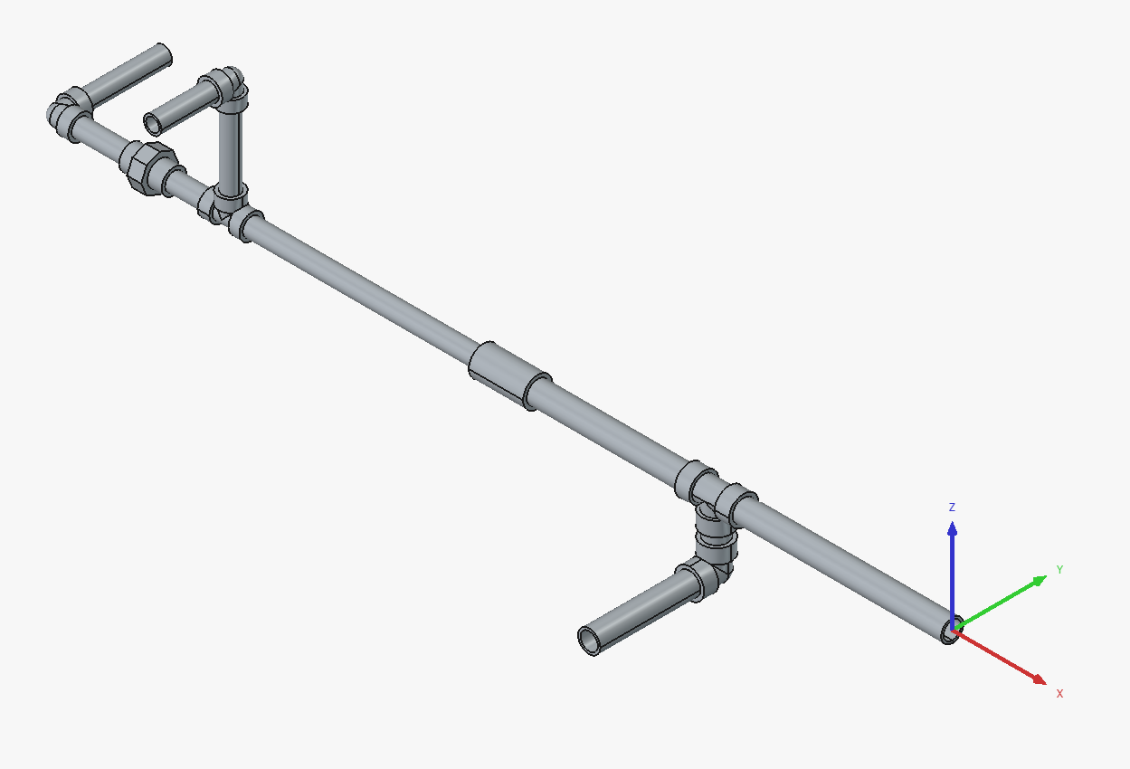
Surprisingly not bad. Not quite right on the lengths of the tee branch pipes, but I didn’t even give it those dimensions so I can’t really complain.
Nobody in their right mind is going to be using AI draftsmen for designing large piping configurations any time soon. But I see this becoming extremely useful for making quick and dirty mockup models for planning inspections, as-builting to capture field changes, and planning small modifications to existing piping for which there is no CAD model. Any other ideas?